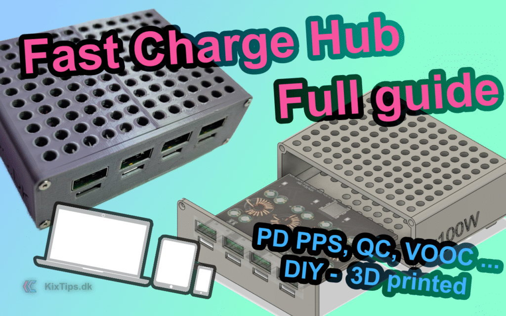
Why build this fast‑charging hub?
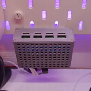
If your desk is littered with mismatched phone chargers, power banks, and laptop bricks, a desktop USB charger hub solves it with one clean device. The KixTips Fast Charger Hub consolidates up to four independent fast‑charge channels (USB‑C PD 3.0/PPS, QC, AFC, FCP/SCP, VOOC/DASH*) in a compact, 3D‑printed enclosure. Powered from a stable 24 V power supply, it unlocks 20 V/3 A PD for laptops and tablets, while still serving phones, earbuds, controllers, and more.
This build emphasizes:
- a minimal, airflow‑friendly enclosure designed around a 4‑in‑1 SW3518 PCB,
- safe wiring with a rear DC barrel jack, and
- repeatable assembly using heat‑set inserts and countersunk screws.
- VOOC/DASH depend on SW3518 (not 3516). See “Protocol support” below.
Update 2026: The project has been ported to MakerWorld.
NEW! An optional Ikea Skadis pegboard mount is now included in the print profile from MakerWorld. The guide below has been updated.
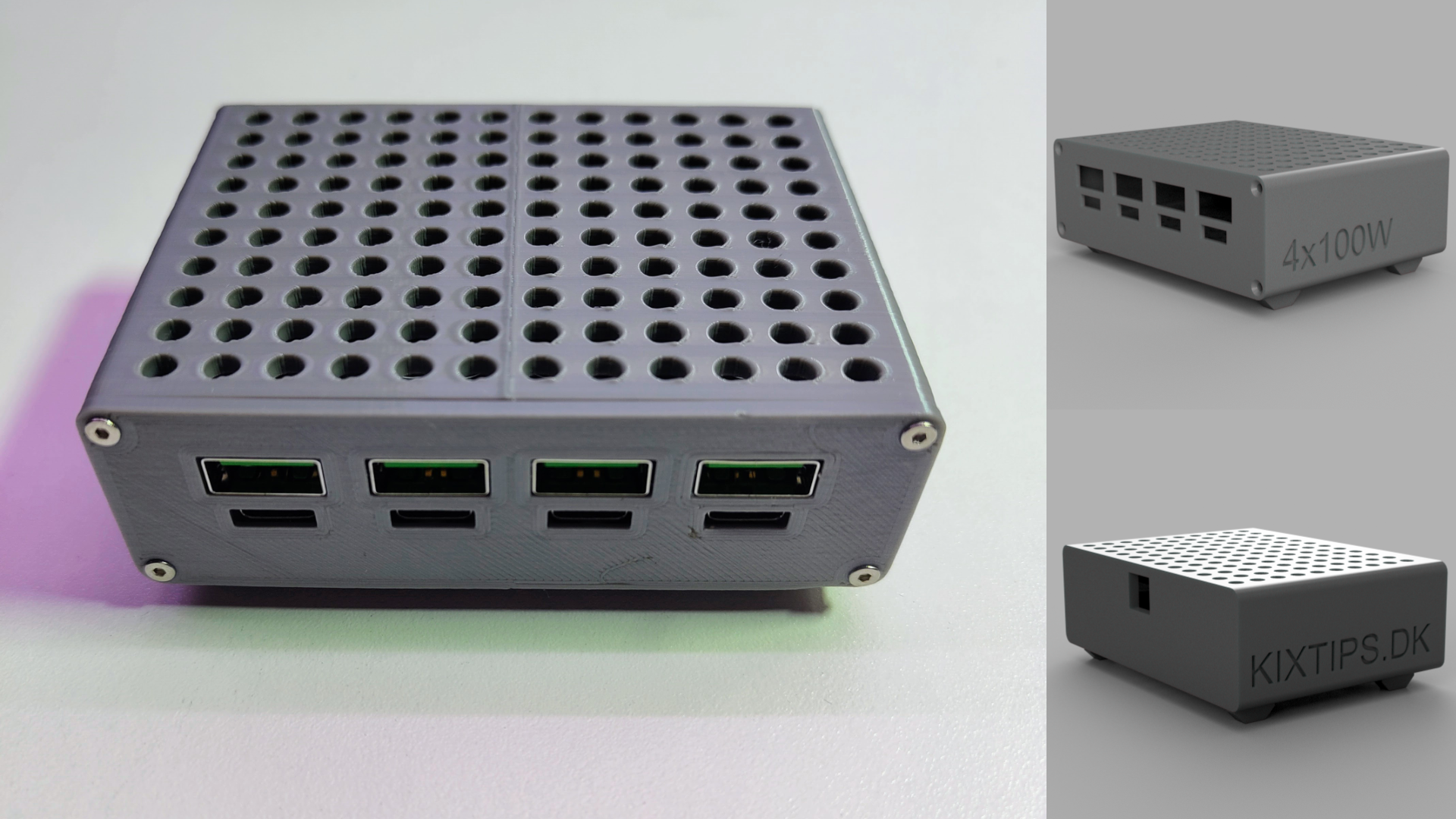
Design overview (features)
- Core: One consolidated PCB hosting 4× SW3518 fast‑charge channels (each with USB‑A and USB‑C).
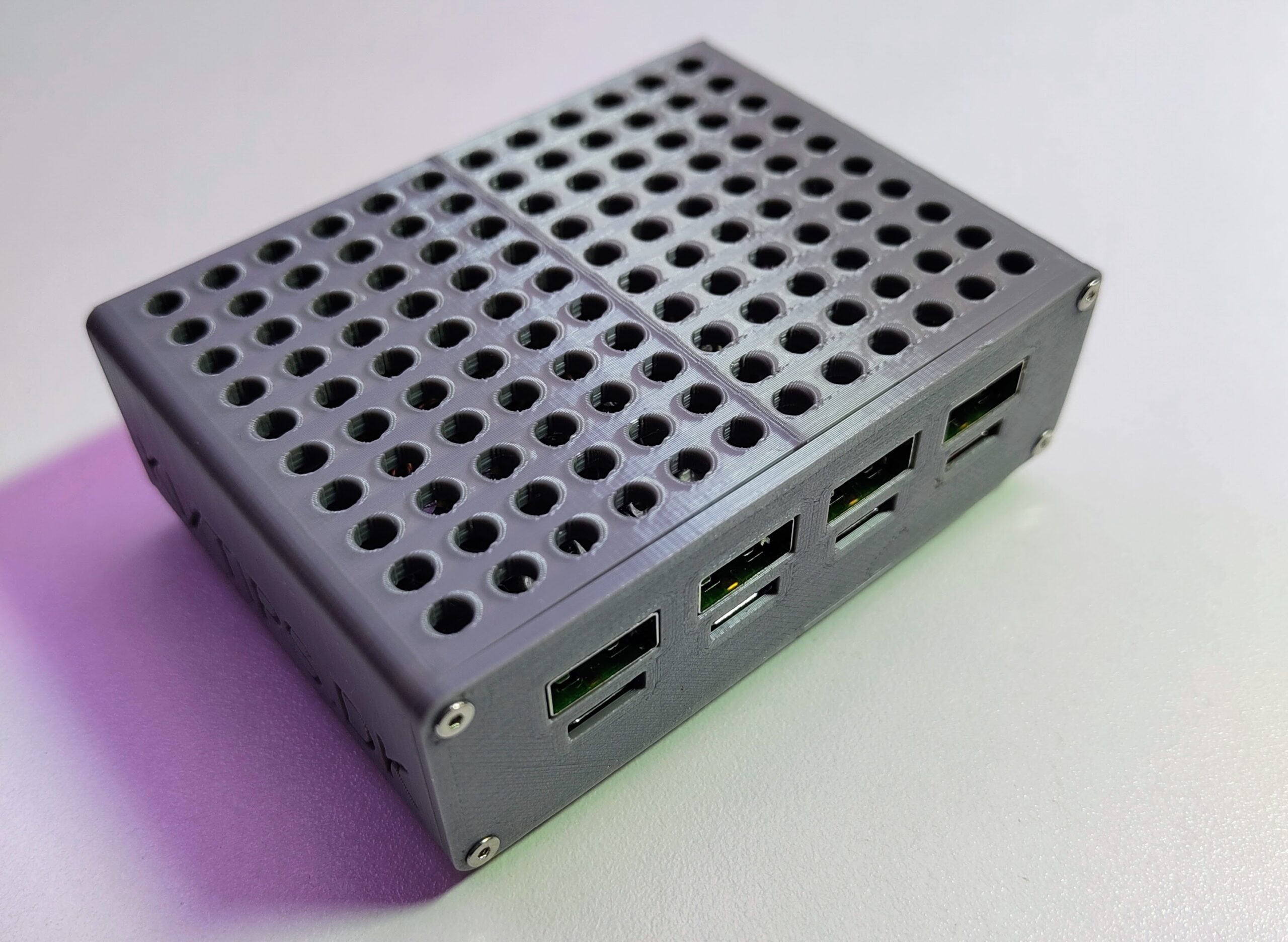
- Dimensions: W: 93 mm, H: 63 mm (incl. feets), D: 69 mm.
- Power: External 24 V DC input via rear 5.5 mm × 2.1 mm jack. 24 V is selected because SW3518 enables 20 V PD only when input >21 V.
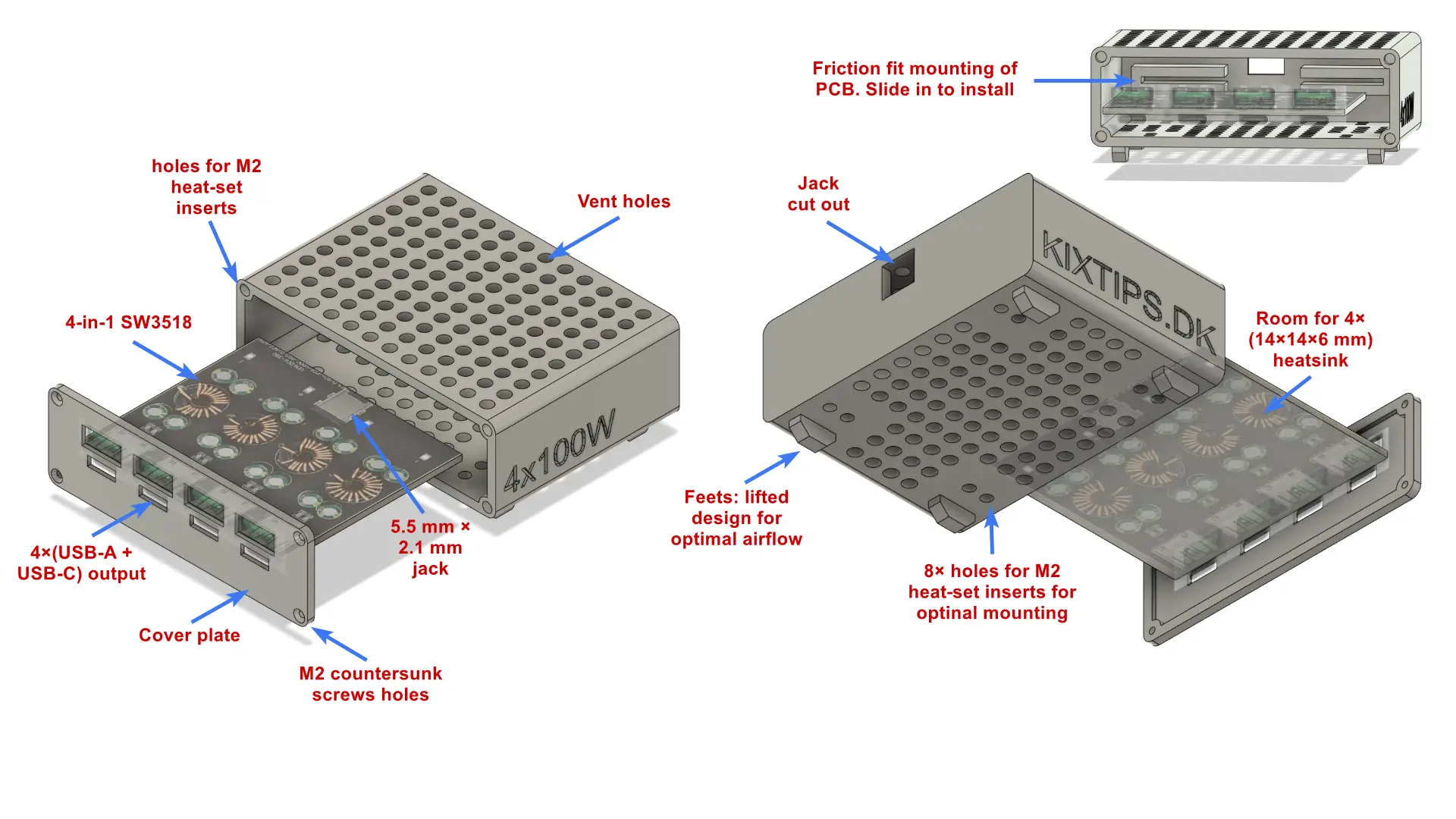
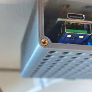
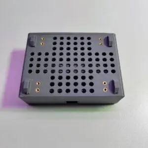
- Enclosure: Two‑part 3D‑printed shell (base + cover plate) with aligned cut‑outs for eight ports, vented top/bottom, small feet, and M2 heat‑set inserts for durable assembly.
- Thermals: Passive airflow plus stick‑on heatsinks on each SW3518 IC. Note: the enclosure is designed for passive cooling only and does not include internal space for a fan. For sustained high loads, consider external airflow or remixing the model to add a fan cavity and power it via a 24 V→12 V buck converter.
- Status: Per‑channel LED: blue = ON/5 V (constant when powered), red = fast‑charge.
- Modularity: Underside bosses sized for additional inserts in case you want wall/under‑desk mounting.
3D Print Files
Download the 3MF print profile or individual STL files from MakerWorld.
- Enclosure.stl — main body housing the 4‑in‑1 SW3518 PCB and rear DC jack.
- Cover‑plate.stl — front cover with eight port cut‑outs and four countersunk holes.
- Skadis Mount.stl – Attach this mount to the enclosure using screws. Allows you to hang it on an Ikea Skadis pegboard.
Suggested print settings
- Material: PETG recommended for heat resistance (PLA works with good ventilation).
- Layer height: 0.20 mm
- Walls: 3–4 perimeters
- Infill: 20–30 %
- Supports: None for the cover; minimal for the base, mainly around the feet (since the part is printed with the jack side down).
- Orientation: Print the cover plate flat on its largest face; print the enclosure with the jack side down for most optimized print support and print time.
If this design helped you, consider supporting the work — Donate here.
Bill of Materials
The products below are affiliate links.
4‑Way SW3518 Module (main board)
https://s.click.aliexpress.com/e/_oDHX3nn
Context specs / notes: Input 6–32 V; PD3.0/PPS, QC4+/QC3.0, Huawei SCP/FCP, Apple 2.4 A, Samsung AFC, VIVO 9V/2A, MTK PE2.0, VOOC/DASH on 3518 only. One fast‑charge port per channel; using USB‑A and USB‑C simultaneously on one channel forces 5 V. For PD 20 V/3 A, supply input must be >21 V and use a compliant USB‑C to C cable.
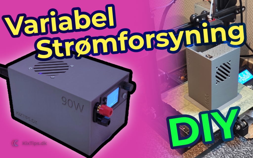
Power Supply — Mean Well LRS‑350‑24 (24 V / 350 W)
https://s.click.aliexpress.com/e/_oEod30l
Selected for reliability & headroom; 24 V enables 20 V PD on SW3518. 350 W is adequate since all four channels are rarely maxed simultaneously. (Any reputable 24 V PSU of sufficient rating can work.)
M2 flat head countersunk hex screw kit
https://s.click.aliexpress.com/e/_opjqzpT
or 6 mm length specifically: https://s.click.aliexpress.com/e/_olyNJaV
M2 Brass Heat‑Set Inserts (3 mm × 3.5 mm)
Heatsinks 14×14×6 mm + thermal pads (10 pcs; use 4)
DC barrel connectors 5.5 mm × 2.1 mm (male used)
16 AWG silicone electrical wire
Optional (for heavy sustained loads):
- Buck converter 24 V → 12 V to power a 12 V fan.
Tools (That I use)
- 3D Printer: Creality Ender‑3
- Filament: Geeetech PLA Gray (or PETG for higher temps): https://s.click.aliexpress.com/e/_oFJmXRr
- Edge deburring tool: https://s.click.aliexpress.com/e/_oBWfO8l
- Soldering iron (also for inserts), e.g., Miniware TS101: https://s.click.aliexpress.com/e/_okBt3BR
- Flush cutters, small pliers, hex drivers, multimeter.
Step‑by‑Step Assembly
Safety first: Mains voltage can kill. Adjust and wire your 24 V supply only if you know exactly what you are doing. Disconnect AC before opening or touching any exposed terminals. Use strain relief and proper insulation. If in doubt, consult a qualified professional.
1) Print, clean, and dry‑fit
- Download the 3MF print profile or individual STL files from MakerWorld.
- Deburr edges. Confirm the 4‑way board slides into the base with a snug, friction fit and that the ports align with the cover cut‑outs.
- Check that the DC jack cutout fits your 5.5 × 2.1 mm jack.
2) Install heat‑set inserts
- Heat your iron to ~220–260 °.
- Press M2 heat‑set inserts into the four bosses on the cover (and any underside bosses if you plan to wall‑mount). Keep them square and flush.
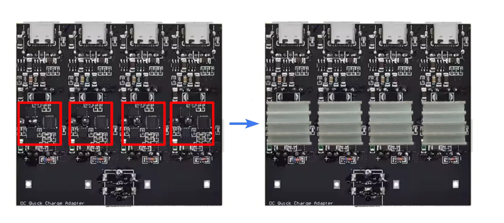
3) Heatsink the SW3518 ICs
- Wipe IC tops with isopropyl alcohol.
- Apply the 14×14×6 mm heatsinks using the included thermal pads before placing the PCB into the enclosure.
- Ensure nothing shorts adjacent components or coils.
4) Mount the 4‑way board
- Slide the SW3518 4‑in‑1 PCB into the enclosure rails.
- It should sit flat; use tiny dots of non‑corrosive adhesive if needed (avoid wicking under ports).
5) Connect the 24 V power supply
- If you’re using the Mean Well LRS‑350‑24 (or similar), mount it separately (e.g., under the desk) with free airflow.
- With AC disconnected, check output trim (usually 23.5–24.5 V).
- Connect the output wires from your 24 V power supply into the screw terminals of the loose male DC plug, then insert it into the female jack on the SW3518 board.
- Polarity matters: center pin is typically +, barrel –. Verify with your multimeter and the PCB silkscreen.
- Fuse appropriately on the DC side (inline blade fuse is a simple option) if you want extra protection.
6) Close the enclosure
- Place the cover plate over the ports.
- Fasten with M2 6 mm countersunk screws.
- If you’re using the Mean Well LRS‑350‑24 (or similar), mount it separately (e.g., under the desk) with free airflow.
8) Power‑on & test
- Plug the 24 V supply into the hub’s DC input.
- Check that the board’s status LEDs light and that each channel provides 5 V at idle.
- Test fast‑charge on one port per channel (USB‑C or USB‑A).
- If you measure current/voltage, use a low‑resistance USB meter so it doesn’t limit fast‑charge.
9) NEW! (Optinal) Skadis mounting option
If you want to declutter your desktop, I’ve modelled a compatible Ikea Skadis mounting option.
- Skadis Mount.stl is included in the print profile, or download it as STL.
- After printing the mount, it screws into the accessory/mounting holes on the bottom of the enclosure (see step 2).
- Hang it facing the ports upwards from anywhere on the board.
Performance & thermal notes
- The SW3518’s efficiency is typically 90–97 %. At moderate total load (≤~200 W across four channels), passive cooling with the provided heatsinks and vents is sufficient in a normal room.
- For sustained high power (e.g., multiple laptops at PD 20 V), consider adding a quiet 12 V fan powered from a 24→12 V buck.
Troubleshooting
- Both ports on one channel only do 5 V → This is by design; SW3518 enables fast charge on one port (A or C) per channel.
- PD 20 V not offered → Ensure input >21 V (use a stable 24 V supply) and a compliant USB‑C to C cable.
- Thermal throttling/instability → Improve ventilation, verify heatsink adhesion, or add a small fan via a buck converter.
- No power → Check DC jack polarity, fuse, PSU output, and continuity from jack to VIN/GND pads.

Wrap‑up
With a reliable 24 V supply, a clean 3D‑printed enclosure, and the 4‑way SW3518 board, you’ve built a compact, desk‑friendly USB‑C PD fast‑charging hub that can replace a drawer full of chargers. The KixTips design keeps airflow and serviceability in mind (heat‑set inserts, countersunk screws, optional mounting points), while the SW3518 module provides wide protocol compatibility for phones, tablets, accessories—and even many laptops.
Warnings & good practice
- Mains safety: Only qualified users should wire or adjust AC‑DC supplies. Always disconnect AC before touching terminals.
- Thermals: Provide free airflow; do not cover vents.
- Current paths: Use appropriate gauge wire and quality cables, especially for high current phone protocols.
- Compliance: This is a DIY project and not certified as a commercial charger; use at your own risk.
Disclaimer
This guide is for educational purposes. You assume full responsibility for the build, wiring, safety, and any resulting damage, injury, or data loss. The author provides no warranties, express or implied.
Support the project & share feedback
If this design helped you, consider supporting the work — Donate here.
Questions, ideas, or improvements? Drop a comment below — I read everything and update the model/guide based on community feedback.
Quick reference: Key components
SW3518 4‑way module: https://s.click.aliexpress.com/e/_oDHX3nn
Mean Well 24 V PSU (LRS‑350‑24): https://s.click.aliexpress.com/e/_oEod30l
M2 countersunk screws: https://s.click.aliexpress.com/e/_opjqzpT
M2 heat‑set inserts: https://s.click.aliexpress.com/e/_o2E3Wrb
Heatsinks 14×14×6 mm: https://s.click.aliexpress.com/e/_on8LbWz
DC barrel connectors 5.5×2.1 mm: https://s.click.aliexpress.com/e/_oEiL4jj
16 AWG wire: https://s.click.aliexpress.com/e/_oFOxk5J
Filament (PLA/PETG): https://s.click.aliexpress.com/e/_oFJmXRr
Edge tool: https://s.click.aliexpress.com/e/_oBWfO8l
Soldering iron (TS101): https://s.click.aliexpress.com/e/_okBt3BR